

Declaration of consent: If you click the start button of the video, personal data can be sent to Youtube!
HMIP-OC8-Pro was made for connecting the Homematic (IP) world to the Velux world. It is based on the same concept as the HMIP_OC8_Micro (http://realhdaudio.de/2019/06/27/homematic-ip-controlling-velux-motors-via-arduino-micro-hmip-oc8-micro/).
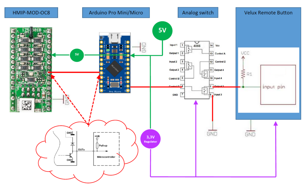
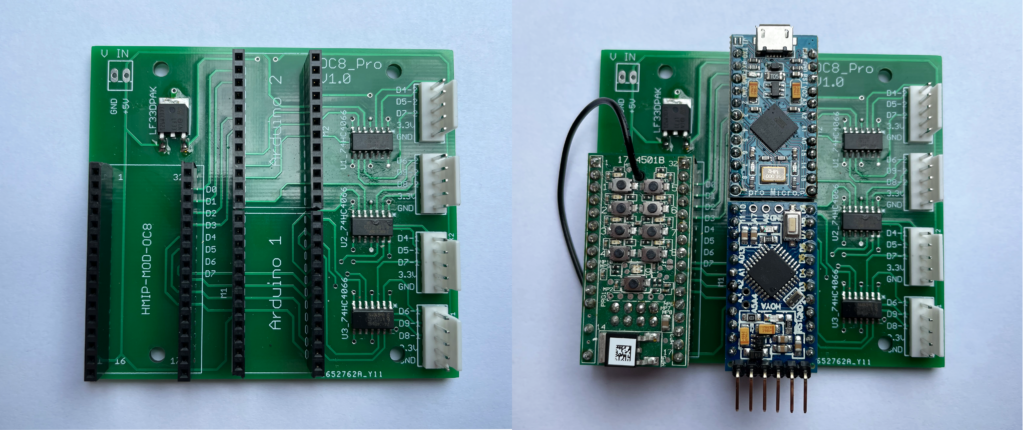
Therefore the HMIP-MOD-OC8 was combined with two Arduino Pro Mini/Micro to control an analog switch (SN74HC4066 or 4066). The analog switch itself is connected to a Velux remote control and is able to pull down the remote´s inputs (buttons). Find the general scheme in figure 1.
Power Supply
The power is provided by an external power supply (5V) to the Arduino Pro Mini/Micro and HMIP-MOD-OC8. A voltage regulator delivers 3,3V for the analog switches (4066) and the Velux remotes. See green and purple lines in figure 1. All devices share the same ground level.
Switching Signals and Levels
Connection between HMIP-MOD-OC8 & Arduino Micro
When a button (or via HMIP App) of the HMIP-MOD-OC8 is pressed the output of the HMIP-MOD-OC8 pulls down a signal to ground level (GND). Therefore, the Arduinos input has to be configured as an “INPUT PULL-UP”. The level on this line is 5V given by the Arduino.
Connection between Arduino Pro Mini/Micro & 4066 & Velux remote
It is not possible to connect the Arduino outputs to the Velux remotes directly, because logic HIGH level of Arduino Micro outputs are always 5V, logic HIGH level of the Velux remote inputs are 3,3V. Therefore, an analog switch (4066) is needed. The 4066 pulls down the Velux remote input when the Arduino´s output gets HIGH.
General Switching
To drive two Velux remotes one Arduino is needed (4 Velux remotes => 2 Arduinos on one pcb possible). If a state of a button on the HMIP-MOD-OC8 changes the Arduino gives a 100 ms impulse and the remote´s input is then pulled down for the same time.
Hardware
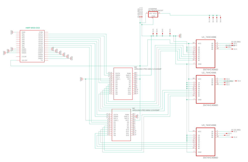
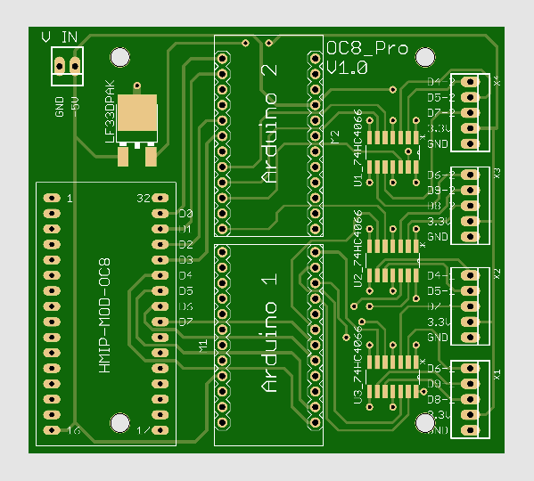
All devices except the power supply and Velux remote are combined on a pcb. The schematic and the pcb layout is made in Cadsoft Eagle 9.6.2.
BOM & Soldering
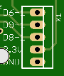
The bill of materials can be found in the manual under „stuff“ and includes every part needed for this project except the housing. The HMIP-OC8-Pro can be connected to (max.) 4 Velux remotes. Figure 4 shows a connector for the Velux remote control. The pins deliver the supply voltage and GND for the remote and 3 analog switch outputs. The first three pins are labeled with the corresponding pins of the Arduino (Example: D6-1 is D6 on Arduino 1) . In case of figure 4 pins will be connected to the Velux remote as follows:
- D6-1 -> remote up button
- D9-1 -> remote stop button
- D8-1 -> remote down button
- 3.3V -> remote positive battery holder
- GND -> remote negative battery holder
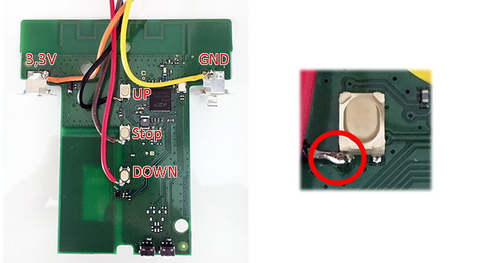
This project uses Velux KLI 313 remotes. Be sure that your Velux remote is already paired with the motor you want to control. How to pair a remote (or a second one) to a single motor can be found in the web. Then open the remote and remove the plastic buttons from the top cover. Solder the cable of the pcb connectors as described in figure 6. Note: Cable color can be different! Double check that everything is connected correctly.
Close the remote again and lead the cabling out of the top cover hole. Connect it to one of the Connectors of the HMIP-OC8-Micro (see figure 7).
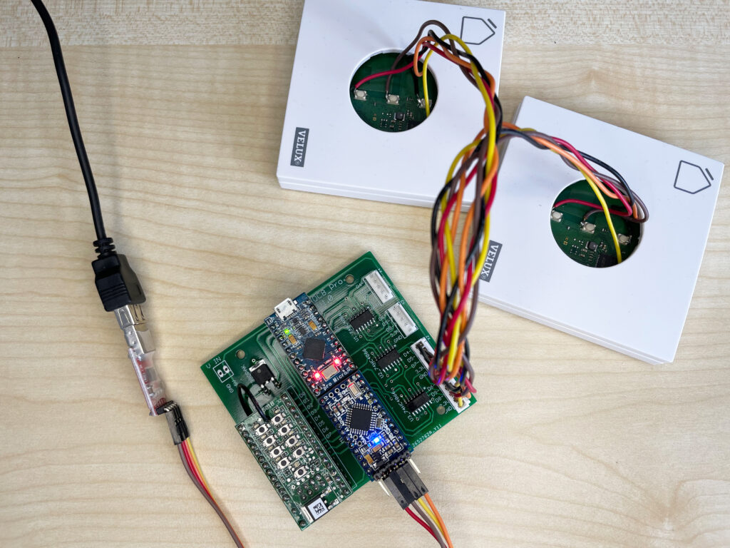
HMIP-OC8-Pro can be testet using USB-power while programming the Arduino Pro Mini/Micro. The external power supply can be done over connector V_In and it is always depending on the product you have. Be aware of polarity. Maximum voltage should be 5V at least 1A.
Arduino Code
Download the Arduino IDE and upload the given code to the Arduino Pro Mini/Micro. To understand what is going on in the code itself please refer to the codes comments. In the default settings the HMIP-MOD-OC8 buttons will act as follows:
- Arduino 2
- Button 1: ON->Motor 1 will go 100% up; OFF->Motor will go 100% down
- Button 5: On->Motor 1 is stopped Off->nothing will happen
- Button 2: ON->Motor 2 will go 100% up; OFF->Motor will go 100% down
- Button 6: On->Motor 2 is stopped Off->nothing will happen
- Arduino 1
- Button 3: ON->Motor 3 will go 100% up; OFF->Motor will go 100% down
- Button 7: On->Motor 3 is stopped Off->nothing will happen
- Button 4: ON->Motor 4 will go 100% up; OFF->Motor will go 100% down
- Button 8: On->Motor 1 is stopped Off->nothing will happen
Homematic IP App
In the HMIP App you are only able to bring the motors to 100% up or down or stop in one position. You will not be able to control intermediate values. When using Homematic (without IP) maybe there you can do it with tricky programming on your CCU.
Files
Please find the manual, PCB-files and Arduino code under „stuff“. I´m would be happy for liking my youtube-channel!
No Warranty
This is a non-commercial project. So there is no warranty for damage or anything else! Use it on your own risk.