
Declaration of consent: If you click the start button of the video, personal data can be sent to Youtube!
Important notes
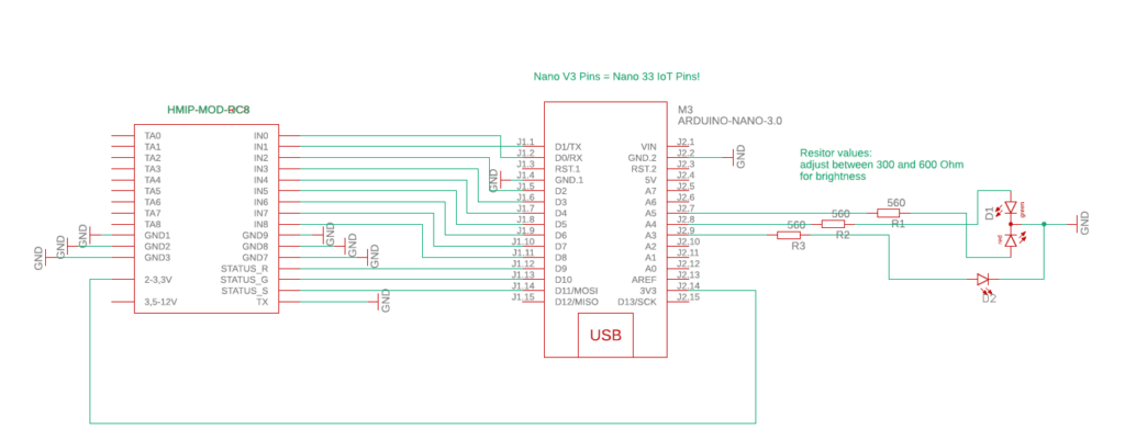
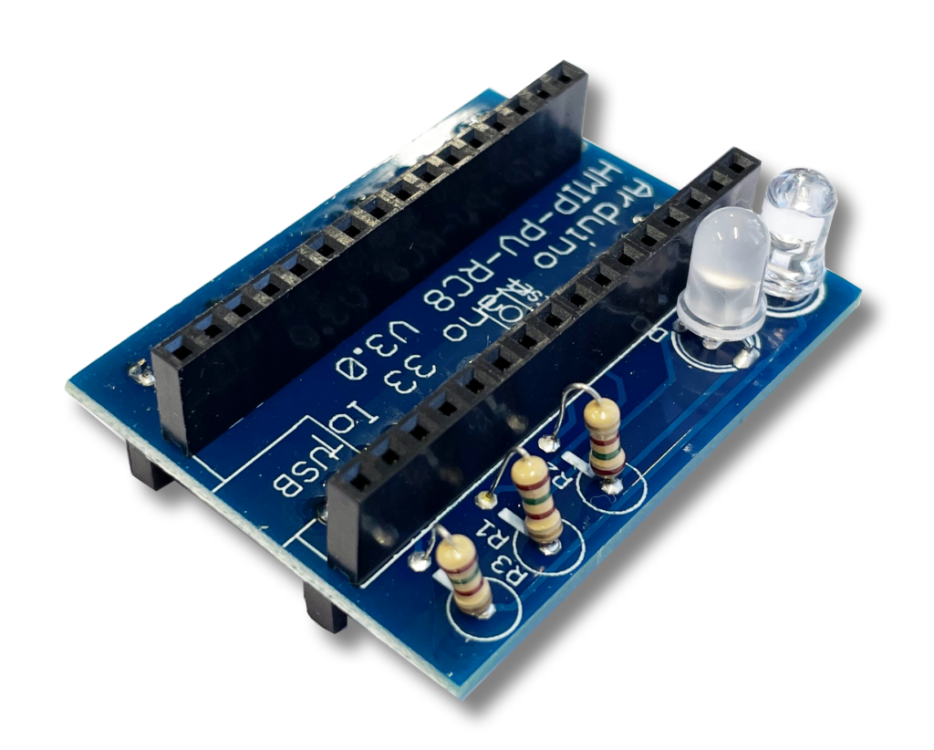
PCB layout V3.0: If you are using the previous pcb layout V3.0 of HMIP-PV-RC8, there is a mistake at the HMIP-MOD-RC8 Pin 1. You can still use the board layout V3.0 but you have to remove pin No. 1 of the HMIP-MOD-RC8! Otherwise the HMIP-MOD-RC8 will be hold in reset, because TA0 is grounded! There is a new pcb V3.1 availlable. It is also recommended to change all resistors (R1, R2, R3) to at least 300-600 Ohm to prevent an overheating µC.
New Software available: There is an additional software version which can reconnect to the wifi when signal is lost, There is also a status read back from HMIP-MOD-RC8 to check for acknowledgement after sending data and a resending function in the case of an error. At least there is reduced pulse length for HMIP-MOD-RC8 to reduce the danger of max. duty cycle error.
Shortly…
HMIP-PV-RC8 detects excess energy from your photovoltaics system (pv excess detection) and reports the information to your Homematic IP system. For this purpose, a microcontroller with wifi interface reads the energy meters multicast message, exports necessary information out of a UDP packet and displays if there is pv excess or not. The whole system is wireless, except the power supply (USB or 5V). Pricing for the components (~50 €) is much less than a big “Home Manager” interface and less complex than a raspberry PI solution. But decide for yourself wether this solution is suitable for your situation.
Story behind it
Yes, we are in photovolthaics club now! We got a small system of around 7 kWh peak without a battery system. So pv power which cannot be used by ourself has to be feed into the public power grid. So “ownconsuption” of sun energy is the order of the day to make our system more profitable. Our car charging station (wallbox) is already able to detect and charge with pv excess. But there was no possibility to tell our Homematic IP smart home system to switch any HMIP device depending on pv excess or no pv excess. To understand lets take a look at the components of our photovolthaics system:
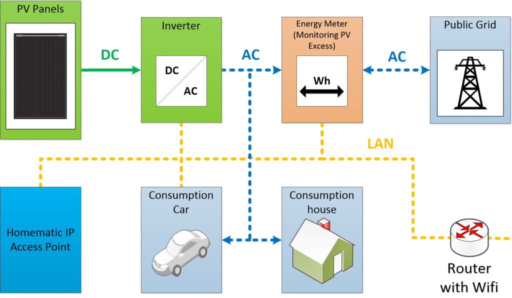
There are two strings of pv panels (22 panels in sum) going into a SMA Tripower inverter (DC/AC) located in the basement. The inverter comunicates with a SMA Energy Meter which is connected to the internet. It also broadcasts all parameters of power consumption, power coming from the panels and power feed into the public grid in a multicast message within the local network. For detailed information for the multicast message please refer to http://www.eb-systeme.de/?page_id=1240 (I am not responsible for this website). The much higher priced SMA Home Manager (instead of Energy Meter) would be able to report pv excess to a couple of smart home systems directly via LAN. But at the moment there only seems to be a solution für Homematic (without IP). So i would either have to switch to another (higher priced) SMA device incl. a more “complex” to handle smart home system or think about a “smart” solution for my problem :-).
Making the HMIP Access Point understand or explore the multicast on it´s own is out of range. So there is the need of somebody else to read the multicast and tell the Homematic IP Accesspoint to switch power consumers when there is pv excess.
How it´s done
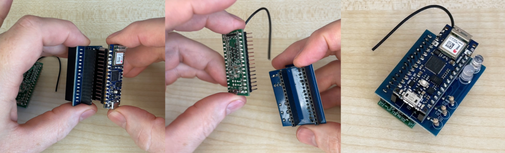
The easiest way is to use a HMIP-MOD-RC8 modul (sender) to talk the HMIP Access Point. Setup via Hommatic IP App is quite easy. To read the multicast i took an Ardunio Nano 33 IoT incl. Wifi modul.
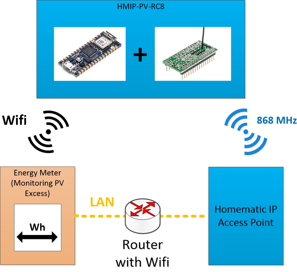
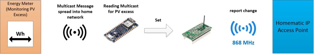
The Arduino is accessing the local network via wifi, reading the multicast spreaded from the Energy Meter. To find out the multicast address and port for your energy meter please refer to this website: https://solaranzeige.de/ (Sometimes there are some problems accessing the website. Sorry, i am not responsible for this website.)
The Arduino (µC) code holds a couple of timers to prevent uncontrolled messaging to the HMIP-MOD-RC8. For example µC waits for about 30 seconds of continious pv excess before telling the HMIP-MOD-RC8 that there is pv excess. And µC also waits 30 seconds before switching from “pv excess” to “no pv excess” to minimize influenzes of clouds covering the sun or anything else.
To give an optical feedback a dual-color led indicates if there is pv excess (green) or not (red). A blue led indicates if a pv excess message is forwarded to HMIP-MOD-RC8.
Hardware
Power Supply
The power is provided by an external power supply (5V) to the Arduinos micro USB slot. The Arduino forwards 3V to HMIP-PV-RC8. So the easiest way to power everything is an USB-Charger connected to the Arduino.
Connection between HMIP-MOD-RC8 & Arduino Nano 33 IoT
All Inputs from the HMIP-MOD-RC8 are connected to digital outputs of the Arduino via a custom pcb. So it is up to you to decide which channels should be activated when there is pv excess. The default programm switches all inputs at the same time. Feel free to programm timers or stepped switching depending of the amount of pv excess.
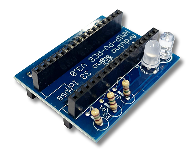
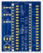
PCB
All devices except the power supply are combined on a pcb. The schematic and the pcb layout is made in Cadsoft Eagle 9.6.2. Both Arduino and HMIP-MOD-RC8 are “stacked” to be as small as possible in size.
BOM & Soldering
The bill of materials can be found in the manual under „stuff“ and includes every part needed for this project except the housing.
HMIP-PV-RC8 can be testet using USB-power while programming the Arduino Nano 33 IoT.
Arduino Code
Download the Arduino IDE and upload the given code to the Arduino Nano 33 IoT. To understand what is going on in the code itself please refer to the codes comments.
Think about the position within your home. Be sure that everyone has it´s wireless connection to his counterparts!
Homematic IP App
In the HMIP App you have to set up the HMIP-MOD-RC8. Now you are able to set automations like switching sockets or something else when HMIP-MOD-RC8 inputs are getting active.
Files
Please find the manual, PCB-files and Arduino code under „stuff“. I´ would be happy for liking my youtube-channel!
No Warranty
This is a non-commercial project. So there is no warranty for damage or anything else! Use it on your own risk.