AK5397 and AK4495 with FPGA Spartan 6; SNR 124 dB ADC, 118dB DAC; up to 384kHz Samplerate; 24 Bit
Something i wanted to do while studiing audio engineering was to build my own small size AD-converter. Because all small DSP systems i found on the market and claimed to be “HD audio” just reached CD quality, like 44,1kHz of sample rate with 16 bit of bit depth. Also their signal to noise ratio (SNR) were limited to approximately 100 dB. But studio standard or in my eyes “realHDaudio” goes far beyond. So there were many things to learn about and my respect for this task let me never try until i came to my second education as an electric engineer. Here I got to know a lot about FPGAs and their programming and i decided to develop a DSP system based on such a chip with the addition of high quality audio converters in my master thesis.
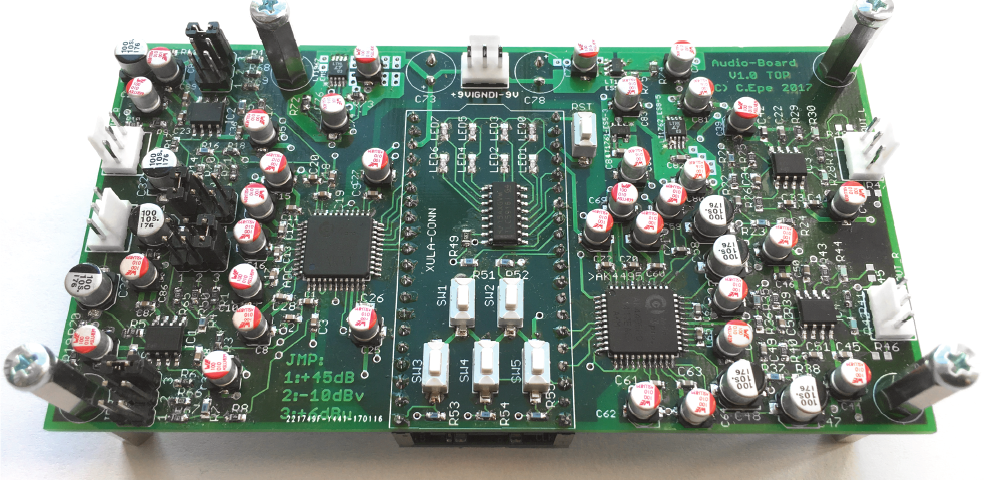
See my first realHDaudio-Board, based on a Spartan6-Board named Xula2. I will decribe the development process and give some electric measurements at the end.
Choosing the main components
There were three main component to choose from the market like a FPGA, the AD- and the DA-Converter. Soldering the FPGA by hand seemed to be impossible for me. So i decided to take a small FPGA development board which can be hosted on my realHDaudio-Board. The Xula2 by XESS was one of the smallest and cheapest boards i found and it is equipped with a prototyping header where almost every FPGA pin can be reached. To get the best ADC and DAC i made a comparison of 28 chips, also codecs. I picked the three best chips from four manufacturers and compared them concerning sample rate, SNR, total harmonic distortion (THD). In the end my decision felt to the AK5397 as the ADC and the AK4495 as the DAC (both made by Asahi Kasei Microdevices, AKM) as they were specified with the best SNR, highest possible sample rate and bit depth. Even the AK4497 is spezified with better SNR, but for 5dB less noise you have to pay an eight times higher price. So the AK4495 seemed to be the better choice to keep my concepts price beneeth 200 €. And i also wanted to compete with other high quality studio converters which got SNRs between 115dB and 123 dB at this time.
Specification given by AKM:
AK5397: 32 bit, 786 kHz SR, 127 dB SNR in stereo mode, -108 dB THD+N
AK4497: 32 bit, 786 kHz SR, 128 dB SNR in stereo mode, -116 dB THD+N
AK4495: 32 bit, 786 kHz SR, 123 dB SNR , -116 dB THD+N
Main concept
The FPGA-Board should be exchangeable and/or stackable on to the realHDaudio-Board like this:

Here the component concept with all needed voltages and communications:

Also the power section made with linear low noise regulators:

The realHDaudio-Board can be driven by two 9V batteries or a power adapter with up to +/-15 Volts. At least 500mA is needed for all components depending on the implemented hardware description of the FPGA, for complex algorithms up to 1000mA can be consumed. In my applikations like some FIR-, IIR- filtering and delay effects i never went beyond 500mA.
Gain structure & analog circuit
A lot of data sheets had to be read to bring all component, regulators, in- and output stages together in a circuit. The audio gain structure should allow studio standard as weel as consumer level and the possibillity to connect a dynamic microphone. Depending on the ADC and DAC analog input and output levels i calculated the following gain structure which had to realized in hardware.

The gain for the analog input stage can be changed via a jumper (see picture JP4) on the board.

The realHDaudio-Board has two channels with balanced in- and outputs. So for the input four of the inverting gain stages are used to get the correct level for the ADC . Analog filtering to prevent aliasing is also done here and can be seen in the overall circuit.
The DACs output has to be filtered analog too. The recommended filter by the DAC manufacturer with modified component values can be seen in the picture below. After my final measurements i realized that this kind of circuit has some ugly characteristics like relativly high THD. Especially when using cheap capacitors. For this problem i spent some more money (1,50€/apiece) for the capacitors in the output stage (C22 and C34 in the picture). There was a nice book from Dougles Self “Small Signal Audio Design” which helped me to solve the THD problem. Thank you Dougles, you made my day :-)!

Digital circuit
The whole circuit can be downloaded under “stuff”. So i will not go in detail with the digital part it. Instead i give you a short overview about the digital concept.
For a great part the circuit for the ADC and DAC follows the recommendations from the their data sheets. The ADC is connected via I²S and is parallel configured by the FPGA. So many FPGA pins had to be spent for it. The DAC is also connected via I²S and allows configuration over SPI connection. So the DAC need less FPGA pins then the ADC. I connected 5 buttons directly to the FPGA to change some program function. To give some feedback for the user the FPGA can communicate via SPI to a led driver chip which can drive 8 leds on the top of the realHDaudio-Board.
After finishing the circuit i made a four layer pcb:

Layer 1 or the top layer (red color) is the main signal layer for analog audio lines and “static” digital lines. Lines for configuration are also placed here because they will not change while playing audio, so they are not critical for the overall audio quality. To keep noise low as possible it is necessary to seperate fast signals like clock signal etc. from the analog part. So I²S lines (blue color) are placed at the bottom layer (layer 4) and are shielded by a ground layer (layer 2) from the sensitive layer 1. In addition the ground layer is splitted in two analog parts on the left and right side and a digital part in the middle. The FPGA is also placed under the board to keep his fast signals away from the top layer. The purple lines in layer 3 are the power lines for different voltages shown in the “power section” above.
Bringing everything together
Oh my god, the first time i am soldering a pcb with smd parts by hand. I watched some tutorials to get familiar with it. The best way for me was to use solder paste, a magnifying glass and surgical tweezers. I only crashed one regulator on my first try (thank god, not the ADC or DAC 🙂 ) because they had the lowest pitch size. I made three boards which took me around 5 hours per board.

The white sockets on the left and rights side can be used to connect balanced jacks or XLR-plugs. The white socket on the top middle is used to power the realHDaudio-Board. So lets do some measurements now!
Measurements
For the measurements i implemented a simple IN/OUT-hardware descritption with a sample rate of 48 kHz into the FPGA. The signal path from analog<->digital<-> analog gives the following specifications.

A SNR of 118 dB can already compete with other high quality converter, but as the measurements are made over the complete signal path it is possible the ADCs SNR can be much higher. To prove this claim you usually have to measure the ADC at his digital end. But it was not possible for me to measure in dual domain. So i used a trick to catch the ADCs SNR by adding 60 dB of digital gain within the FPGA. After that you can measure noise at the DACs output which is mostly consisting of noise from the ADC. Subtracting the 60 dB digital gain leads to an ADC SNR of around 123,9 dB.
Frequency Response is also quite linear (note the y axis):

Here the spectrum with some THD from the analog output circuit (input signal was not fullscale here):

Linearity deviation:

Summary
I think this project will give some information about my work for my first realHDaudio-Board. The overall audio quality is very good. I implemented a vocal channel strip to show some useful functions. I catched it in the video below. In my next project i will change the outputs anti aliasing filter to a better version to get the THD from a good to a very good value. Leave a comment if you want. I will give some download material under stuff.
VIDEO
comming soon…